The Foundation of Solenoid Operated Device Symbols
In the realm of industrial automation, the precise control of fluids—whether liquid or gas—is paramount for efficient and reliable operations.

What is a solenoid valve?
At the heart of many such control systems lies the solenoid valve, an industrial device governed by electromagnetic forces. Functioning as a critical type of actuator, the solenoid valve utilizes an electromagnet to generate a magnetic field, which in turn manipulates the movement of a valve core. This action alters the valve’s opening and closing state, thereby controlling the flow of fluids. As such, the solenoid valve is a fundamental element in automation, playing a crucial role in adjusting parameters like direction, flow rate, speed, and pressure of the medium. Given their operational principle based on electromagnetism, they can also be conceptually linked to magnetic valve symbols, although the primary terminology focuses on their solenoid-driven nature. The solenoid valve is a prime example of a solenoid operated device, a broader category encompassing various mechanisms activated by solenoids. To effectively design, implement, and maintain systems incorporating these vital components, a standardized method of representation is essential: the solenoid operated valve symbol.
This article aims to provide a comprehensive understanding of solenoid operated valve symbols, exploring their significance, components, variations across industries, different types, and the considerations for international application, particularly concerning products from Chinese manufacturers. We will delve into the information conveyed by these symbols and their crucial role in ensuring the seamless operation of fluid control systems.
The Indispensable Importance of Solenoid Operated Valve Symbols
The solenoid operated valve symbol is not merely a graphic representation; it is a fundamental tool that underpins various critical stages in the lifecycle of a fluid control system.
- Design Phase:During the initial design of hydraulic or pneumatic systems, the solenoid operated valve symbol provides engineers with an intuitive understanding of the required solenoid valves.
- System Planning: By examining the symbols, engineers can readily determine the type of solenoid valve needed (e.g., two-position two-way, three-position four-way), the quantity required, and their intended working positions within the system. For instance, in designing the control system for an automated production line, engineers can use these symbols to plan a logical fluid control scheme that ensures precise control over each mechanical action.
- Selection and Matching: The information embedded within the solenoid operated valve symbol, such as rated flow, working pressure, and data relevant to the solenoid symbol electrical aspects like solenoid coil voltage, is crucial for selecting the appropriate solenoid valve. This ensures compatibility and proper functioning with other components in the system. For example, in a high-pressure hydraulic system, engineers can accurately choose a solenoid valve capable of withstanding the pressure by referring to the symbol’s specifications, thus guaranteeing the system’s stable operation.
Installation and Commissioning Phase
The solenoid operated valve symbol plays a vital role in guiding the practical implementation of fluid control systems.
- Installation Instructions: Technicians rely on these symbols to perform correct installation, including identifying the appropriate installation location and orientation for the solenoid valve, as well as the correct connection directions for the associated pipes. When installing a pneumatic system, for example, the air inlet, air outlet, and working ports can be accurately connected to their corresponding pipelines by following the symbols, thereby preventing installation errors.
- Debugging Assistance: During the system debugging phase, the solenoid operated valve symbol aids technicians in comprehending the system’s control flow. By comparing the symbols with the actual operating conditions, technicians can verify whether the power-on sequence and timing of the solenoid valve meet the design specifications, facilitating the adjustment of the valve’s action. For example, when debugging the control system of an industrial robot, technicians can check the working state of the solenoid valve against the symbols to ensure the robot’s movements are accurate.
Maintenance and Troubleshooting Phase
The utility of the solenoid operated valve symbol extends to the ongoing maintenance and repair of fluid control systems.
- Daily Maintenance: The symbols help maintenance personnel understand the function of each solenoid valve within the system, making it easier to conduct regular inspections and maintenance of critical components such as the solenoid coil and valve core. In a water supply and drainage system, for instance, maintenance personnel, understanding the solenoid valve’s role from its symbol, can focus on checking its sealing and electromagnetic performance.
- Troubleshooting: When system malfunctions occur, the solenoid operated valve symbol serves as an essential diagnostic clue. Maintenance personnel can use the fault symptoms and the symbols to pinpoint which solenoid valve might be the source of the problem. This allows them to then investigate potential causes such as solenoid coil damage or valve core sticking. For example, on an automobile production line, if a pneumatic device fails, maintenance personnel can use the system diagrams with solenoid valve symbols to locate the relevant valve for inspection and repair. This can also involve checking aspects related to the solenoid symbol electrical, such as the integrity of the coil’s wiring and connections.
Decoding the Meaning Within Solenoid Operated Valve Symbols
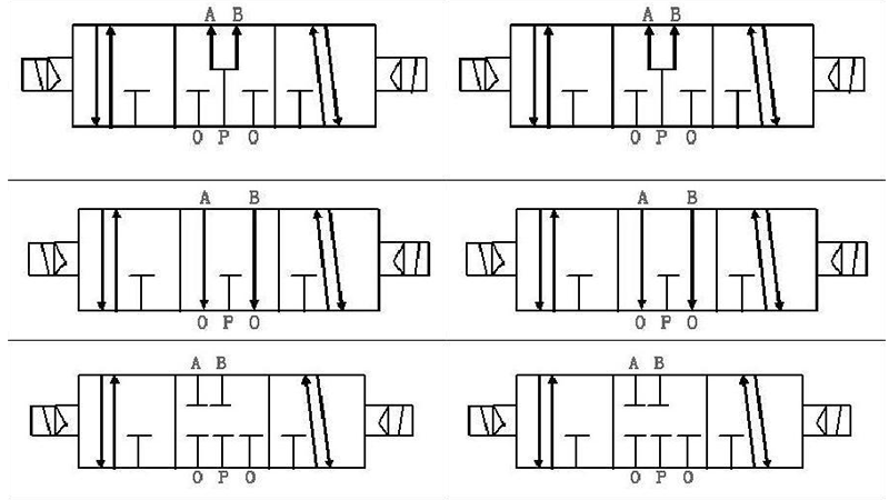
The solenoid operated valve symbol is a concise yet informative graphical representation, typically composed of several key elements: boxes, arrows, characters, and an indication of the number of interfaces. Understanding these components is crucial for interpreting the symbol’s meaning and the function of the represented solenoid operated device.
- Box: Each box within the symbol represents a distinct working position, or “position,” of the solenoid valve. For example, a solenoid valve with three boxes indicates a three-position valve capable of operating in three different states.
- Arrow: Arrows within the boxes indicate the direction of fluid flow within the solenoid valve in a specific working position. It is important to note that the arrow’s direction signifies the connection of oil or gas circuits, not necessarily the actual direction of fluid movement in the broader system.
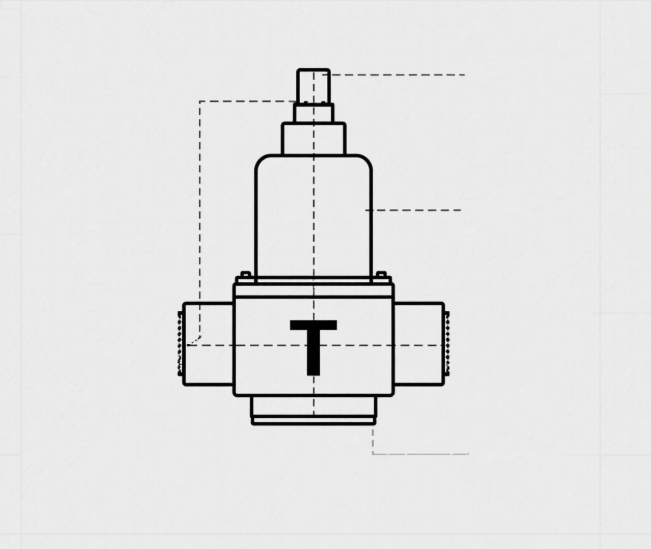
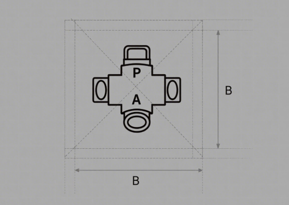
- Character: Characters are used to denote the interface connection status and control signals of the solenoid valve. Common characters include “P” for the inlet port, “A” and “B” for ports connected to the actuator, “R” for the outlet or return port, and “T” to indicate a blocked interface.
- Number of Interfaces: The number of external connections to the boxes in the symbol indicates the number of “ways” the solenoid valve has. For instance, a two-way valve has two external ports.
Collectively, these elements of the solenoid operated valve symbol provide a clear and standardized way to represent the functionality and connectivity of a solenoid operated device within a fluid power system.
The Role of the Solenoid Valve Symbol Electrical Schematic
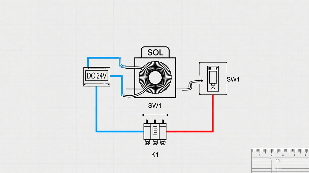
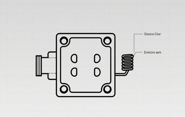
While the primary solenoid operated valve symbol focuses on the fluidic aspects of the valve, the solenoid valve symbol electrical schematic is crucial for understanding its electrical control mechanism. These schematic diagrams illustrate how the solenoid coils are integrated into the electrical control circuit that governs the valve’s operation. The solenoid symbol electrical, typically represented by a coil symbol, indicates the electromagnetic actuator that drives the valve core.
The solenoid valve symbol electrical schematic shows the electrical connections to the solenoid coil(s), including power sources, control signals, and any associated switches or relays. By examining this schematic, technicians and engineers can understand how energizing or de-energizing the solenoid coil(s) leads to a change in the valve’s working position and thus alters the fluid flow. The source material mentions that numerous electrical schematic diagrams of solenoid operated valve symbols exist, providing a glimpse into their variety. Understanding these schematics is essential for diagnosing electrical faults related to the solenoid valve and ensuring proper electrical control of the solenoid operated device. The consistent and accurate representation of the solenoid symbol electrical within these schematics is vital for effective troubleshooting and maintenance.
Diverse Requirements Across Industries for Solenoid Operated Valve Symbols
The specific requirements for solenoid operated valve symbols can vary significantly across different industries. This variation stems from the diverse application scenarios, functional requirements, and system complexity inherent in each industry.
- Process Industries: In sectors like chemical, petrochemical, and pharmaceutical, solenoid valves are predominantly used to control the flow of fluids (gases and liquids) to maintain the stability and safety of production processes. The demand for solenoid operated valve symbols in these industries emphasizes the need to clearly indicate the type of solenoid valve (e.g., direct-acting, pilot-operated), its function (e.g., normally open, normally closed, self-locking), and its connection relationships (e.g., air inlet, exhaust port, working port). On flow charts with control points (PID diagrams), the symbol must accurately reflect the valve’s position and connections within the actual production process, enabling technicians to quickly identify and operate it.
- Machinery Industry: In the mechanical industry and electromechanical integration involving gas and hydraulic transmission systems, solenoid valves primarily control the movement of pneumatic or hydraulic actuator components. Here, the crucial aspect of the solenoid operated valve symbol is its ability to concisely and clearly indicate the working status of the solenoid valve (e.g., fluid flow direction when powered or unpowered) and the connection method. In pneumatic or hydraulic diagrams of mechanical systems, the symbol needs to clearly display the valve’s control logic and its effect on the actuator, facilitating system debugging and maintenance.
- Automated Control Systems: In automation control systems, the solenoid valve is a key actuator, and its symbol must accurately represent its position and function within the overall control architecture. These systems often involve intricate control logic and sensor networks, so the solenoid operated valve symbol must be able to integrate seamlessly with the symbols of other control elements (such as sensors and controllers) to form a complete control system diagram. In the design documents and drawings for these systems, the symbol needs to precisely convey the valve’s control logic and its execution effect, aiding technicians in programming and debugging the system.
- Other Industries: Beyond these major sectors, numerous other industries, including food processing, textiles, and papermaking, have their own specific requirements for solenoid operated valve symbols. These needs are typically linked to the industry’s unique process requirements, operating environment, and the type of fluid medium being controlled. To accommodate these diverse needs, the solenoid operated valve symbol must possess a degree of flexibility and adaptability. For example, in the food industry, the symbol might need to explicitly indicate the valve’s material and hygiene grade, while in the textile industry, it might need to denote characteristics like corrosion and wear resistance.
Exploring Different Types of Solenoid Operated Valve Symbols
The representation of solenoid valves in symbolic form varies depending on the type of valve and the fluid it controls.
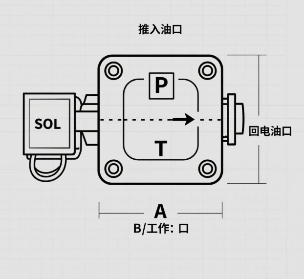
Hydraulic Solenoid Operated Valve Symbol
In addition to the basic elements indicating working position, port connections, and electromagnetic control, the hydraulic solenoid operated valve symbol includes markings specific to hydraulic systems. Typically, “P” represents the oil inlet, “T” the oil return port, and “A” and “B” the working ports for connecting hydraulic cylinders and other actuators. These symbols are used in hydraulic circuits to illustrate the control of hydraulic oil flow direction, pressure, and flow rate to drive hydraulic actuators.
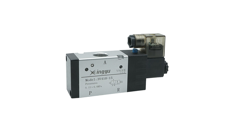
Pneumatic Solenoid Operated Valve Symbol
The pneumatic solenoid operated valve symbol shares similarities with its hydraulic counterpart but is used in pneumatic systems. Commonly, “P” denotes the air inlet, “T” the exhaust port, and “A” and “B” the working ports connected to pneumatic actuators like cylinders. These symbols illustrate the control of compressed air flow direction, thereby governing the extension and retraction of cylinders and other pneumatic actions, commonly found in automated production lines and pneumatic tools.
Single Solenoid Operated Valve Symbol
The single solenoid operated valve symbol typically consists of a box representing the valve body, lines within the box showing the valve core’s position, and a symbol for the solenoid coil. For instance, in a simple single-control two-position two-way solenoid valve, applying power to the single solenoid moves the valve core to control the opening or closing of the fluid path. The solenoid symbol electrical is clearly depicted as a coil connected to one side of the valve symbol, indicating that actuation occurs when this single coil is energized.
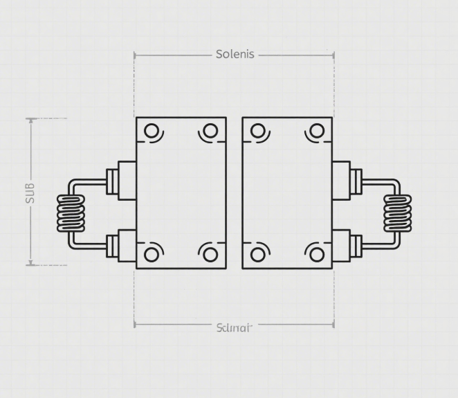
Double Solenoid Operated Valve Symbol
The double solenoid operated valve symbol features two solenoid coils. It generally uses two boxes to represent the different working positions. Each box corresponds to the valve core’s position and port connection status when one of the solenoid coils is energized. Double solenoid valves are often used in three-position valves, where the two solenoid coils control the valve core’s movement in two opposite directions. When both coils are de-energized, the valve core typically returns to a central position, allowing for more complex fluid control functions, as seen in some hydraulic or pneumatic systems requiring precise control and multiple operating states. Each solenoid coil is represented by its own solenoid symbol electrical.
3-Way Solenoid Operated Valve Symbol
The three-way solenoid operated valve symbol is characterized by having three ports. The connection relationship between these ports in different working positions is usually indicated by lines and markings within a square box. The most common types are two-position three-way and three-position three-way valves. A two-position three-way solenoid valve has two working states: in one state, fluid flows from port P to port A, and in the other, fluid flows from port P to port B (or port P connects to port T, etc.). The three-position three-way solenoid valve offers an intermediate position function, enabling various fluid control strategies.
Connecting Symbol Clarity to Manufacturer Quality
While not the primary focus of the provided material, the clarity and standardization of solenoid operated valve symbols in product documentation can be indicative of a manufacturer’s commitment to quality. Manufacturers who prioritize clear and accurate symbols, aligned with international standards, demonstrate a level of precision and attention to detail that often extends to their production processes. This is particularly relevant when considering choosing a Chinese solenoid valve factory and manufacturer. Factors such as certification status (e.g., ISO 9001), advanced production technology, and thorough detection methods all contribute to quality assurance. Clear and consistent solenoid operated valve symbols, including accurate representation of the solenoid symbol electrical, serve as a part of this overall quality framework, facilitating better communication and understanding between the manufacturer and international buyers.
International Buyers’ Demands for Chinese Solenoid Valve Symbols
When Chinese manufacturers of solenoid valves cater to the international market, there are specific demands regarding the solenoid operated valve symbols used in their product documentation and system diagrams. These demands are crucial for facilitating international design communication, collaboration, and the effective use of solenoid operated devices.
- Symbol Standardization: International buyers typically require that Chinese manufacturers adopt internationally accepted standards for their solenoid valve symbols, such as IEC standards. This standardization is essential to avoid misunderstandings and ensure that engineers and technicians across different countries can interpret the symbols correctly.
- Symbol Accuracy: The symbols must accurately and clearly depict the solenoid valve’s working position, port connections, and electromagnetic control method, including precise details about the solenoid symbol electrical. This accuracy is vital to ensure that buyers correctly understand the product’s functions and specifications.
- Product Consistency: The functions and parameters represented by the symbols must be consistent with the actual performance and specifications of the physical solenoid operated device. Any discrepancies can lead to system malfunctions and operational issues for the buyer.
- Multi-language Labeling: Including multi-language labels, such as English, alongside the symbols is highly beneficial for international buyers with diverse language backgrounds, making it easier for them to understand and operate the equipment.
Furthermore, international buyers expect clear and detailed solenoid valve symbol electrical schematic diagrams that accurately represent the electrical control circuitry of the solenoid valve. Consistent representation of the solenoid symbol electrical across all product documentation and schematics is also paramount for clear understanding and effective integration into international systems.
The Enduring Significance of Standardized Representation
the solenoid operated valve symbol is far more than a simple illustration; it is a critical language within the world of fluid control and industrial automation. A thorough understanding of these symbols, encompassing their components, variations, and the information they convey about solenoid operated devices, is essential for engineers, technicians, and maintenance personnel alike. From the initial design stages through installation, commissioning, maintenance, and troubleshooting, these symbols provide a standardized and efficient means of communication. As Chinese manufacturers increasingly serve the global market, adhering to international standards for solenoid operated valve symbols, including accurate solenoid symbol electrical representation and clear solenoid valve symbol electrical schematic diagrams, is crucial for ensuring product acceptance, facilitating seamless integration into international systems, and building strong relationships with international buyers. The accurate and consistent use of these symbols ultimately contributes to the efficient and reliable operation of fluid control systems worldwide. Understanding the nuances of different types, such as the single solenoid operated valve symbol, further enhances the ability to interpret and work with diverse system designs.